


1.2 Features
Adopts ultrasonic flow measurement technology, no mechanical rotating parts, low pressure loss, which reduces the power consumption of water pumps and the water supply cost of enterprises.
The ultrasonic measurement method ensures higher accuracy within the measurement range, high reliability, and it can work at any flow point for a long time with strong anti-electromagnetic interference capability.
Adopts a low-power design scheme, and a single battery can work continuously for more than 6 years.
Low starting flow and high accuracy class.
When faults such as low power supply voltage and ultrasonic transducer failure occur during operation, it has the functions of fault judgment, recording and display. It can monitor the battery, temperature and flow in real time, and record the date of the fault and the effective data at that time.
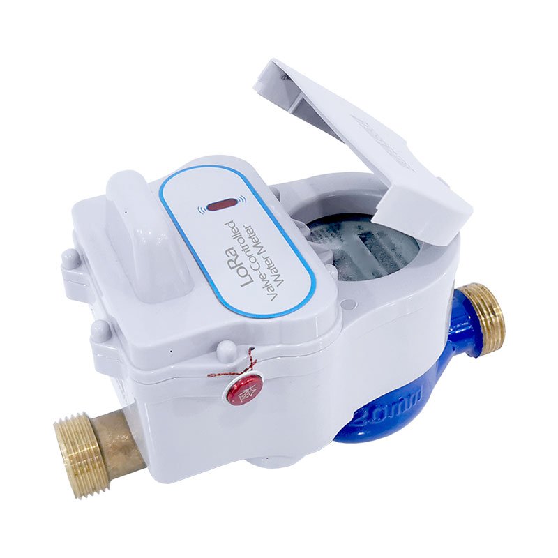
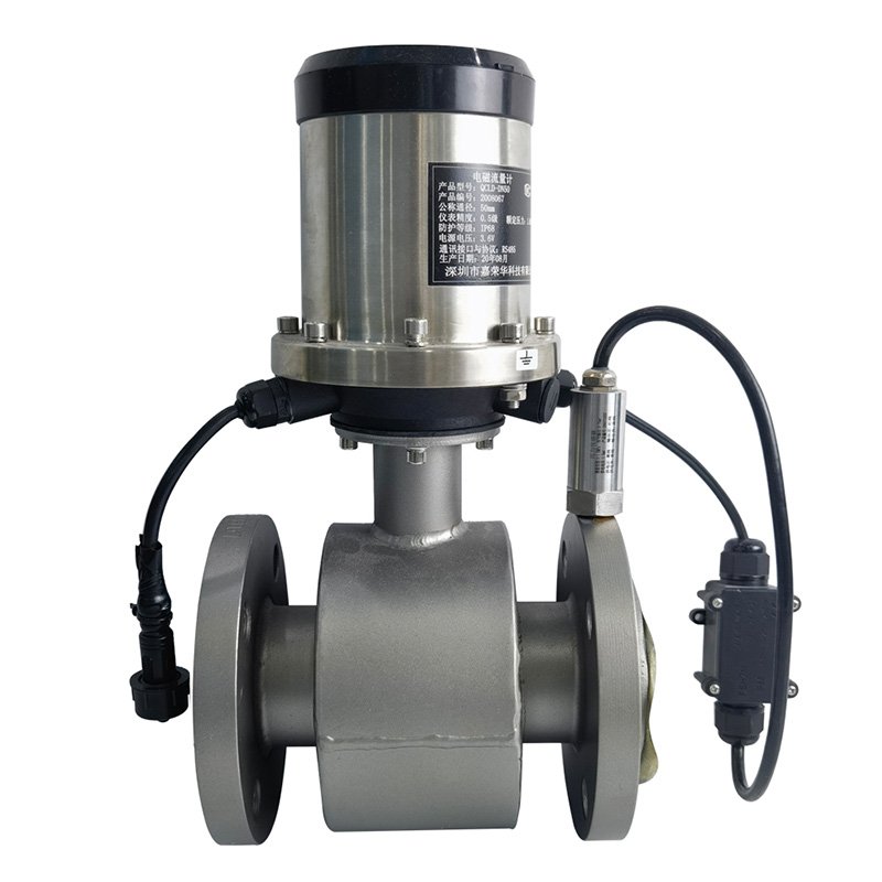
It can realize flow measurement and temperature measurement, and has a variety of optional communication methods such as RS-485, M-BUS, NB-IoT, LoRa, 4G and LoRaWAN.
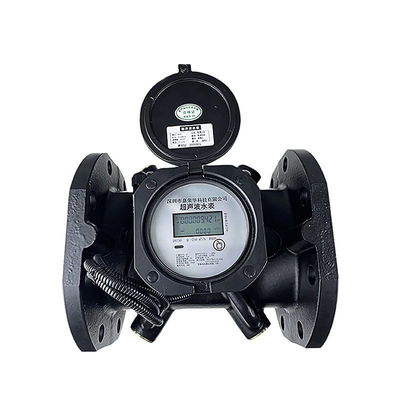
Full-range caliber design from DN15 to DN300, which can meet the needs of different scenarios.
2.1 Technical Parameter Table
| Measured Medium | Domestic water (other liquids need to be customized) and the pipeline must be full of liquid |
| Accuracy Class | Class 2 |
| Range Ratio | R160/R200/R250/R400 |
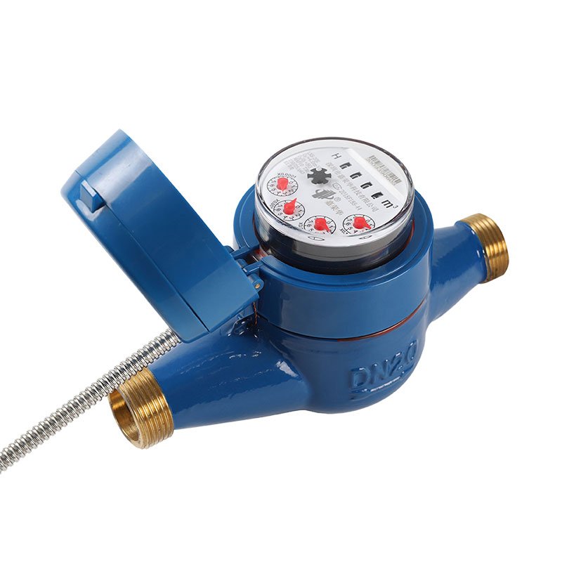
| Nominal Diameter | DN15~DN40 |
| Maximum Allowable Working Pressure | 1MPa |
| Environmental Class | Class O |
| Temperature Class | T30, T50, default is T30 |
| Upstream Flow Field Sensitivity Class | U0 |
| Downstream Flow Field Sensitivity Class | D0 |
| Electromagnetic Compatibility Class | Class E1 |
| Communication Interface | RS-485/M-BUS/Infrared/NB-IoT/LoRa/4G/LoRaWAN |
| Power Supply | Built-in lithium battery (3.6V) |
| Protection Level | IP68 |
| Buttons | Touch buttons |
| LCD Display | LCD displays cumulative flow, instantaneous flow, as well as status indicators and units |
| Data Storage | Uses EEPROM to store data, and automatically records the cumulative flow of the previous 24 months |
| Measurement Cycle | 1~4 times/second |
| Average Power Consumption | <100uA |
2.2 Flow Range
Small-caliber Parameters:
R400/R250 Flow Parameters:
| Nominal Diameter (mm) | DN15 | DN20 | DN25 | DN32 | DN40 |
| Accuracy Class | Class 2 | Class 2 | Class 2 | Class 2 | Class 2 |
| Common Flow Q3 (m³/h) | 2.5 | 4 | 6.3 | 10 | 16 |
| Range Ratio Q3/Q1 | 400/250 | 400/250 | 400/250 | 400/250 | 400/250 |
| Minimum Flow Q1 m³/h) | 6.25/10 | 10/16 | 15.8/25.2 | 25/40 | 40/64 |
| Dividing Flow Q2 (m³/h) | 10/16 | 16/25.6 | 25.2/40.4 | 40/64 | 64/100 |
| Overload Flow Q4 (m³/h) | 3.125 | 5 | 7.9 | 12.5 | 20 |
| R Value | Flow (m³/h) | 40 | 50 | 65 | 80 | 100 | 125 | 150 | 200 | 250 | 300 |
| 160 | Q1 | 0.16 | 0.25 | 0.40 | 0.63 | 1.00 | 1.60 | 2.50 | 4.00 | 6.30 | 10.00 |
| Q2 | 0.25 | 0.40 | 0.63 | 1.00 | 1.60 | 2.50 | 4.00 | 6.30 | 10.00 | 16.00 | |
| Q3 | 25 | 40 | 63 | 100 | 160 | 250 | 400 | 630 | 1000 | 1600 | |
| Q4 | 32.25 | 50.00 | 78.75 | 125.00 | 200.00 | 312.5 | 500.00 | 787.50 | 1250.00 | 2000.00 | |
| 200 | Q1 | 0.10 | 0.16 | 0.25 | 0.40 | 0.63 | 1.00 | 1.60 | 2.50 | 4.00 | 6.30 |
| Q2 | 0.16 | 0.26 | 0.40 | 0.63 | 1.00 | 1.60 | 2.50 | 4.00 | 6.30 | 10.00 | |
| Q3 | 25 | 40 | 63 | 100 | 160 | 250 | 400 | 630 | 1000 | 1600 | |
| Q4 | 31.25 | 50.00 | 78.75 | 125.00 | 200.00 | 312.50 | 500.00 | 787.50 | 1250.00 | 2000.00 | |
| 400 | Q1 | 0.063 | 0.100 | 0.160 | 0.250 | 0.400 | 0.630 | 1.000 | 1.600 | 2.500 | 4.000 |
| Q2 | 0.10 | 0.16 | 0.25 | 0.40 | 0.63 | 1.00 | 1.60 | 2.50 | 4.00 | 6.30 | |
| Q3 | 25 | 40 | 63 | 100 | 160 | 250 | 400 | 630 | 1000 | 1600 | |
| Q4 | 31.25 | 50.00 | 78.75 | 125.00 | 200.00 | 312.50 | 500.00 | 787.50 | 1250.00 | 2000.00 |
2.3 Performance Error Curve

2.4 Pressure Loss Curve

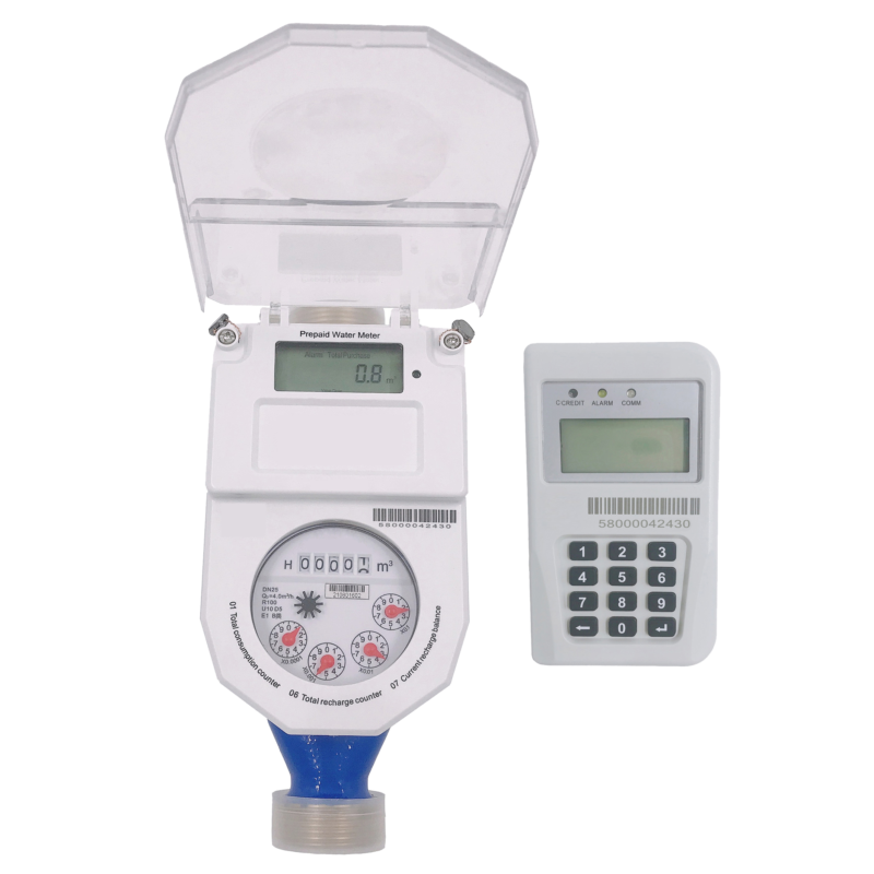
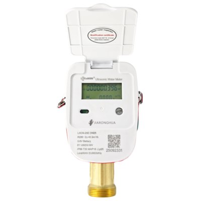
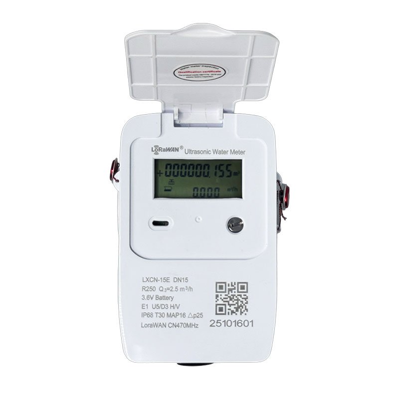
3.1 Product Description

1.Water Meter Caliber: “LXCN” indicates an ultrasonic water meter; “25” means the water meter caliber is 25mm; “E” stands for a smart water meter.
2.Q3: Common flow rate; R250: Range ratio (Q3/Q1)
3.T50: Water temperature range is 0℃ ~ 50℃
4.△p25: Pressure loss class
5.IP68: Protection rating (waterproof and dustproof)
6.E1: Electromagnetic environment class
7/8. U0: The length of the straight pipe section required on the upstream side of the water meter is 0 times the nominal diameter (theoretically, no straight pipe section is needed); D0: The length of the straight pipe section required on the downstream side of the water meter is 0 times the nominal diameter.
9/10. H: Horizontal installation; V: Vertical installation
11.MAP16: Maximum allowable working pressure is 1.6 MPa
12.Battery Rated Voltage: 3.6V
13.Production Date
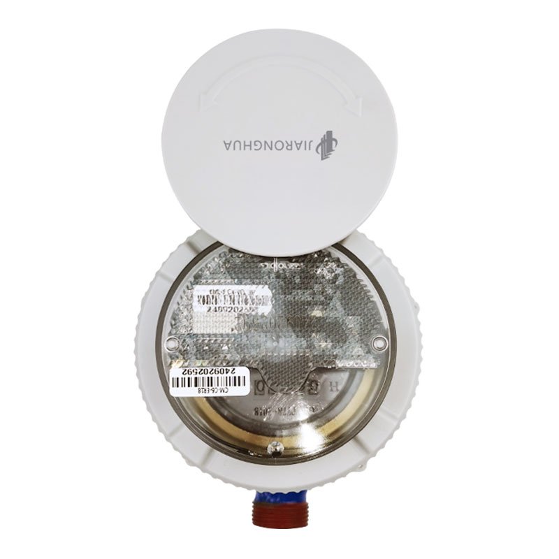
14.Cover
15.Water Meter Type
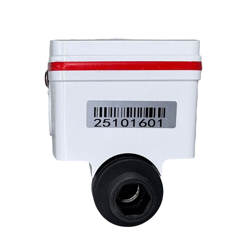
16.Infrared Sensor
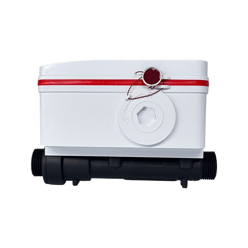
17.Lead Seal
18.Touch Button
19.Meter Number QR Code
20.Meter Number
21.Battery Compartment
22.Water Meter Caliber
23.Water Flow Direction
24.Valve Position
3.2 LCD Display

LCD diagram
The LCD adopts a combination of segmented digital codes and units for display, which can show data such as instantaneous flow and cumulative flow, meeting the needs of different users for resolution and range. Meanwhile, the LCD can display various status information prompt symbols to show the system operation status in real time. The meanings of various prompt symbols are as follows:
| Symbol | Meaning |
| Cumulative flow unit | |
| Instantaneous flow unit | |
| GAL | Gallon |
| L | Liter |
| GPM | Gallons Per Minute |
3.3 Menu Operation
Press the button on the main interface. When the iconappears, keep pressing the button until the icon shows up, then release the button immediately. At this point, the infrared function is activated, and parameters can be read and written via infrared. If you continue to hold the button for another 2 seconds without releasing it until the icon appears, then release the button to enter the verification mode. If you keep holding the button for another 2 seconds after the icon appears until the icon shows up, the water meter will connect to the network and report data.
: Infrared activated, parameters can be read and written via infrared.
: Enter verification mode.
Water meter connects to the network and reports data.
Only the battery symbol and “3.60” are displayed: Indicates the battery rated voltage is 3.6V.
A leftward arrow is displayed: Indicates cumulative reverse flow.
A rightward arrow is displayed: Indicates cumulative forward flow.
No arrow is displayed: Indicates the total cumulative flow of forward and reverse flows.
“01” is displayed: Indicates the first half of the meter number.
“02” is displayed: Indicates the second half of the meter number.
3.4 Status Indicator Explanation
| Nominal Diameter (mm) | Length L (mm) | Width W (mm) | Height H (mm) | Thread D (mm) |
| 15 | 165 | 90 | 105 | G3/4B |
| 20 | 195 | 90 | 150 | G1B |
| 25 | 225 | 90 | 117 | G1 1/4B |
| 32 | 180 | 90 | 132 | G1 1/2B |
| 40 | 200 | 90 | 132 | G2B |
| 50 | 200 | 125 | 215 | – |
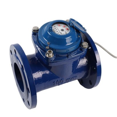
| Flange Specification | Nominal Diameter (mm) | Pipe Section Length L (mm) | Flange Face Width D (mm) | Pipe Section Height (mm) | Bolt Hole Diameter × Quantity N – Ø |
| Flange | 50 | 200 | 165 | 125 | 18×4×2 |
| 65 | 200 | 175 | 170 | 18×4×2 | |
| 80 | 220 | 185 | 185 | 18×8×2 | |
| 100 | 250 | 220 | 180 | 18×8×2 | |
| 125 | 250 | 230 | 230 | 18×8×2 | |
| 150 | 300 | 285 | 240 | 22×8×2 | |
| 200 | 350 | 340 | 295 | 22×12×2 |
5.1 Installation Requirements
1)All water meters undergo strict calibration and inspection before leaving the factory. Calibration, maintenance, replacement of parts, and repair must be carried out by professional technicians.
2)The water meter must be installed strictly in accordance with the designed location;
3)unauthorized movement is strictly prohibited.
4)The lead seal of the water meter must not be damaged; otherwise, the warranty will be invalid.
5)Before installing the instrument, ensure that the pipeline has been thoroughly cleaned. In accordance with the household metering design requirements, a filter must be installed before the water inlet of the ultrasonic water meter. The filter must be cleaned and maintained regularly to prevent debris in the pipeline from affecting the measurement.
It is recommended to install valves on the pipelines before and after the instrument to facilitate future maintenance.
8)The water meter calculator (display) must not be immersed in water.
9)The quality of the supplied water should comply with relevant regulations.
The water meter is a measuring instrument and must be regularly verified in accordance with national standards. The battery should be replaced during verification, and battery replacement must be performed by professional personnel.
5.2 Installation Location and Precautions
Installation diagram
3.Points A, B, and E are not recommended installation points. Point A is the pipeline water inlet, where the flow field is relatively complex, affecting the flow measurement accuracy. Point B is a downward-flowing pipeline, where the back pressure at the rear end of the water meter is low, making it easy to generate air bubbles that affect the measurement accuracy. Point E is the highest point of the pipeline layout, where air bubbles are likely to form in the pipeline, resulting in abnormal measurement.
5.3
Step 1
Install a general ball valve at the pipeline inlet end.
Step 2
Install the inner joint and filter in sequence.
Step 3
Install the dedicated joint.
Step 4
Install the gasket inside the inner joint.
Step 5
Install the water meter, and install the gasket and dedicated joint at the water meter outlet end.
Step 6
Install the general ball valve.
2.The ultrasonic water meter should be stored in its original packaging. The storage environment should have a temperature range of -5℃ ~ 40℃, a relative humidity not exceeding 70%, and no corrosive gases in the air.